Our interest at this point is how we perceive space, objects, their dimensions and their visual relations with us.


Human evolution has given us a complex physiological visual system with two eyes, placed at an average horizontal distance of 2 ½ inches or  6.35cm apart. This measurement is called Interocular Distance (IO) and it enables a horizontally parallaxed view of the world that is in harmony with the physiology of human vision.

Parallax means the ability to see an object in two different ways. It is a displacement or difference in the apparent position of an object viewed along two different lines of sight, and is measured by the angle or semi-angle of inclination between those two lines. 

Our side-by-side eyes have lenses that carries images of real objects to the retinas and they also have capabilities of different functions, like movement in different directions, focus, convergence on chosen points of interest.

Two retinas receive images in a two-dimensional form, and transform their luminosity into electrical impulses that travel through optic nerves, transmitting the images to our brain.


The Human Interocular Distance


The Interocular Distance between the left and right eyes yields two slightly different images on their respective retinas; this difference is called Retinal Disparity.

Retinal Disparity is caused by Parallax which, by definition, means the ability to see an object in two different ways.

The human brain fuses both two dimensional images into one cognitive sensation called Stereopsis, which let us perceive space and objects of the real world in a stereo mode.


So, our material world is in 3D and we see it in Stereo.


It is very important to understand that our visual system captures, process and “projects” the images of space and objects in their places in our brain.

This analogy helps us to understand how to capture and reproduce stereo images using photo/cinematographic systems and the relationship between capturing and projecting stereo images..

by Affonso Beato, ASC, ABC

                                                                                                                                                                                                           version 05.27.14


Today the two major claims on watching stereo movie presentations are :

the need of the use of glasses and the visual/brain stress present in some stereo programs.

The first claim still needs research and development time to resolve auto stereoscopic solutions for medium and large screens and/or a big jump on  a technological direction towards plenoptic and light field (computational) cameras or feasibly holography.


This text is about the second claim – not having comfortable stereo presentations.


For that we need to subtract the known statistically fact that more than ten percent of the world population have ophthalmological impairments that impedes seeing in stereo and/or have discomfort watching stereo presentations. The extension and the scientific specifics of this problem wouldn’t allow this matter to be discussed here.


Uncomfortable presentations are caused by bad stereography, which is the consequence of lack of scientific stereographic information and the utilization of wrong technical procedures in the production, post-production and exhibition stages.

With the economical success of theatrical stereo presentations in the past four years, the movie industry did rush into a myriad of products, some shot in stereo, some converting 2D materials to stereo without any guidance. Right now, our movie industry lacks of Recommendations and Standards for Production, Distribution and Exhibition of stereo products.


Before defining Comfortable Stereography would be important to understand how the human visual apparatus perceives the physical world in stereo and after how we capture and reproduce images in stereo.

The understanding of the difference between 3D and Stereo is important to our didactical process.


Our stereo visual perception of the world


It would seem obvious, but our world is in 3D and we perceive it with the sensations of volume and depth and we call it seeing in stereo.

The real world is composed of space and objects with many physical dimensions.

Space has three dimensions, width, height and depth, geometrically represented by x, y and z axes.

Time and movement are expressed by the change of object’s positions in Space.

Understanding Comfortable Stereography


Divergence and Maximum Screen Parallax


Since Screen Parallax promotes Stereopsis, it is important to control its maximum value to achieve a good sensation of stereo depth without producing visual stress.

It is known that we can support, without stress, up to 1.0 degree of divergence (0.50 degrees for each eye), and that becomes an important factor in achieving comfortable stereoscopy, so when you are shooting a scene in stereo, controlling Maximum Screen Parallax becomes the main task of the Stereographer.


Although there are not yet standards on this field, the industry informally agrees and recommends that Maximum Negative and Positive Parallax should not exceed 3% of the Screen Width, except in occasional circumstances.

Camera Sensor/Lens Calculator


Defining Comfortable Stereography


Since we can’t change the lenses  of our eyes , the way we see the world in stereo cannot be changed physiologically and its parameters and limitations must be taken in account and respected when will try to reproduce and show it with photo/cinematographic systems.


From what we have stated on human vision we should carry three principal factors: the Interocular Distance between our eyes (IO), our human Field of View (FOV) and our Convergence Point, being IO and FOV constants and Convergence a variable for our future calculations..

We see the world with these three factors daily and they need to be taken in consideration when we create and view stereo presentations.


We define Comfortable Stereography as a set of procedures that respect geometric parameters of these three constants of the human visual system.


Among the existing mathematical theories the one that fits more this axiom is the Ortho Stereo Condition [ Vd = M * fc  ] (where Vd is the Viewer Distance from the screen, M is the frame Magnification, fc is the Focal Lens).


Ortho means equal in Greek and by bringing these variables close to or equal to the human vision constants ( IO , FOV and Convergence) , we will have trigonometric formulae that would guide as on the best procedures on to shoot, edit and project stereo imagery.


When shooting stereo images is recommended to use, as much as possible, a Lens that would be the closest to the Normal Lens, so these variables will be held close to the Human Vision, making the stereo presentation visually more comfortable.


We will study on how to approach the Ortho Stereo Condition building an Ortho Stereo Model, but first lets see how we can get there.


Reproducing the stereo world with photo/cinematographic systems


From the caves drawings of 35000 years ago to modern photography, human kind has tried to copy the world visually using two dimensional renderings, although historically many artists, using perspective and lighting give us the feeling of our three dimensional world.


The Art and Science of Stereoscopic imagery, what we could call the birth of Stereo 3D, dates from 1833, when a British mathematician and inventor – Sir Charles Wheatstone created the Stereopticon ( image below ), even before the invention of Photography.

More on this subject on: STEREO 3D PRESENTATIONS - HISTORY, PRESENT AND FUTURE

Convergence


When you converge your eyes to a very close point, like your finger close to your nose, it causes the image of an object far away to duplicate due to excessive disparity, but if you converge directly on the distant object, the image of your fingers will duplicate due to excessive disparity as well and also shows how fusion can be broken in our brain process.

Since the beginning of Stereography, we have been simulating the physiology of the human vision to achieve Stereopsis. Today we use a pair of cameras emulate the Left and Right eyes to achieve it.


The physical size of photographic and cinematographic cameras and lenses have always imposed limitations in the capture of images with two cameras using our human Interocular Distance, but human ingenuity has developed numerous stereo rig designs to solve this problem.

Digital Cinematography and computation power are giving us many possibilities to correct errors in the process and has even given us many new tools to enlarge our esthetic and artistic capabilities.


Creating a Stereo Visual Model


Using some geometric symmetries, let us create a simple stereo system wherein we proceed from observing an object in space, to photographing it using a binocular camera system and reproducing it on the screen projection, with the same dimensions of the real object.

We will call this a simple Ortho Stereo Model , which is a simulation of the Human Ortho Stereo Condition.


Viewing


Let us say for example that we are observing a 0.5m width cube on a 3m width space, 6m distant from us and we want to reproduce it with its original dimensions in a stereo projection.

Capturing


Lets then shoot it with two cameras from the same distance (6m) using equal focal length lenses that achieve the same horizontal field of vision (FOV) angle which we are observing the object (approximately 28 degrees) and our lenses we would give us an Image Width of 3m.

Let’s suppose that the Interaxial Distance (IA) between the two lenses axes would be 0.0635m = 6.35cm = 2.5 inches. Equal to our Human Interocular Distance (IO) so that the camera IA = the Human IO.

Projecting


Now we project the left and right images onto a Screen Width of 3m, adjusting the distance and the Projection FOV to achieve the projected cube with a 0.5m width.

Screen Parallax


When simultaneously projecting a pair of 2D images on the screen we would observe (not using stereo glasses) a difference between them. This difference is called Screen Parallax, when translated to our retinas and from there to our brain, this Parallax give us Stereopsis;

more Screen Parallax yields more Stereopsis.


In order to separate the Left and Right camera images to our respective Left and Right eyes, we can encode and decode the images by the use of anaglyphic Red / Cyan color separation ( a very old technique from still photography that works on the principle that Red and Cyan are color opposites), polarizing or intermittent temporal flashing techniques.

The most common implementation today, uses 90 degree phase differentiated sequential projection on a silver screen to an audience wearing similarly phase differentiated passive polarized glasses.

A simple Ortho Stereo Model


Building this system we achieve symmetries between Viewing, Capturing and Projecting:


Camera distance from Cube = Viewer distance from Real Object

Camera distance from Cube = Viewer distance from Screen

Camera interaxial = Viewer Interocular ( IA = IO )

Camera FOV = Projection FOV (fc)

Image Width = Screen Image ( M = 1 )

In this scenario, the Captured Cube Width = the Projected Cube Width ( M = 1 )

Positive Screen Parallax


If now we place our cube at 9m, but keep our Convergence Point Distance  at 6m, you will see that our screen parallax increases and our projected object seems to be behind the screen, deep on the Z axis.

If we follow the symmetrical procedures of the this simple system, we will achieve a comfortable stereo reproduction view of our cube, since we converged our both eyes and cameras to the cube, we would get a minimum of disparity and Screen Parallax and also a minimum of Stereopsis.


The Ortho Stereo Model is a simple visual presentation tool that would help us to establish constants and variables mathematical elements, that control stereo systems.


We will build a more complex system to achieve Stereo Depth, but before we do, let’s get more acquainted with the factors and terminology about the things that we want to reproduce in stereo placed along the Z axis.


Convergence Point


If we converge our stereo cameras to an object (at 6m) and stereo project it, we will achieve a minimum of screen parallax and the object seems to be at the screen plane. This point is called Convergence Point, also known as ZPS or Zero Parallax Setting.


Convergence is how we control the depth of the objects on the Z axis in relation to our Screen and/or the position of the Screen in relation to Depth.

By setting the Convergence Point we are establishing the Screen Plane in relation to the objects in the Scene.

The closest Convergence Point Distance and Angle on one of the two planes promotes excessive disparity in our retinas and brain, breaking fusion and Stereopsis, and causing visual discomfort. Breaking Fusion is the primary and major factor of uncomfortable stereography.


Field of View


Human vision encompasses a very wide Field of View. If we include our peripheral vision we can perceive shapes and movements on a 180 degrees horizontal angle. We call this peripheral vision.


We can even see our own noses, but our subjective attention gives us a focused average field of view of about 28 degrees, the equivalent of a 40mm lens on a Super 35mm cine camera frame format. This angle promotes a constant perspective in our vision.

In photo and/or cinematography, this would define a Normal Focal Lens.

To find a Normal Lens for  your camera sensor and lens set configuration you can use existing calculators, like this iTunes App in the figure below.

The Ortho Stereo Model with Depth Range


Now that we have more terminology on stereographic elements on the Z axis and understand their visual consequences on space, let us make our viewing/capturing/ projecting system a bit more complex, introducing 2 more cubes ahead and behind of our converging point to illustrate Stereo Depth Range as another factor.


The Ortho Stereo Model serves as an mathematical basis from which to achieve and control Comfortable Stereography.


Viewing/Capturing/Projecting

Negative Screen Parallax


If now we place our cube at 3m, but keep our Convergence Point Distance at 6m, you will see that our screen parallax increases and our projected object seems to be in front of the screen, closer to us on the Z axis. Observe that the position of the images on the screen (Red & Cyan) are reversed.

Stereo Depth Range


Depth Range in stereoscopy is the distance on the Z axis between the nearest Foreground  object( Znear) and the most distant Background object ( Zfar ) , that interest us in a scene.

The Depth Range that we elected to our model (3m, 6m and 9m) is based on the most common space distances used when we shoot dramatic content, but we can achieve an Ortho Stereo Condition ( IA = IO ) at any convergence distance from the camera, if we place the nearest and furthest objects of the Depth Range equidistant from the convergence point.


Stereo Depth Control


Convergence Point is the distance from the camera to a point in the Z axis where our cameras converge and this is how effectively we control the position of our screen in relation to our Stereo Depth Range or Stereo Budget.


An informal industry Recommendation is that Negative Parallax should not exceed 20% .

Thist means that our Foreground object should not “pop out” of the Screen more than 20% of the Depth Range.


It is important to control the Negative Parallax Percentage in order to minimize the viewer’s ocular muscular stress from having to adjust the position of the Foreground object from shot to shot.

Remember that on a typical theatrical feature presentation we would have an average of 1000 to 2000 shots, it is a lot of work for the eyes to readjust if there are large  differences of Convergence accomodation from shot to shot.


As always in filmmaking, one can break the rules if the violation of this principle is done in a fast shot movement.

Convergence and Excessive Screen Parallax


As a geometric consequence, when we converge two cameras to a point, objects in the Z axis away from the Convergence Point, when projected on a screen will go apart promoting Screen Parallax.


Since more Screen Parallax promotes more Stereopsis, our tendency as stereographers is to push for the maximum of Stereopsis, but there is a critical point where the disparity of the two views of an object becomes so large, that our eyes and brain can no longer comfortabl merge the two images. .


If we bringing the Convergence Point to 3.0 m, we can see that the Screen Parallax of the background cube 9.0m, increases in excess to a point the our projected object splits in two and our brain cannot process fusion and/or Stereopsis . This error in stereographic  procedure is usually the main cause ( sometimes intense) discomfort in stereo presentations.


Look carefully at the values on the image below and see how much the cubes in the background separates and how the Positive Screen Parallax increases. The figure below is only a didactical example, since a Stereographic Calculator would change the IA value in order to avoid Excessive Positive Screen Parallax.

Divergence


Two typical physiologic breaks of fusion from excessive parallax can be caused by circumstances that convert or divert the direction of our eyes as we try to observe and merge two almost identical but excessively separated images simultaneously. This can occurs in both Excessive Positive Screen Parallax,  where our eyes attempt to diverge unnaturally and in Excessive Negative Screen Parallax circumstances, where our eyes attempt to converge to an uncomfortably close angle, causing visual stress as well.

Augmenting the Divergence Angle value causes an increase on the roundness feeling of our shot, but we should keep this value equal or less than 1.00 degrees, to avoid visual discomfort.


Screen Parallax and the Projection Factor


Screen Parallax is the distance between the same point of the same stereo object photographed and project in a screen.

If you think this distance as a segment, you will see that this segment will shrink visually as you move away from and increases if you moove close to the screen, increasing and/or reducind Stereopsis to the Viewer.


So we need to calculate this factor by knowing the Screen Width and the Distance of the Viewer from the screen.


On a stereo projection if you come closer to the screen you will favor the sense of Roundness or Volume on the objects being shown, if you move away from the screen you will favor the sense of Depth of the scene.


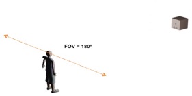
Most films in stereo are mastered for an optimum screen size of between 25 to 40 feet wide, from a recommended viewer distance of 1.5 to 2 screen heights to give viewers just over a 60 degree field of view, with an average  horizontal displacement of 2% of screen width, a number which varies  from shot to shot.  That's a widely acknowledged comfortable 3D viewing experience.


Smaller screens and larger screens factor in, but the more important number to understand is horizontal viewing angle, which is determined by the distance of the viewer to the screen.  If we view (for example) an HD 1920 x 1080 pixel HD image projected onto an approximately 40’ x 22.35 ’ movie screen from a distance of one and a half screen heights (or about 33.5’) trigonometry tells us our horizontal viewing angle is approximately 62 degrees, yielding an average of  just over 30 pixels per degree.  At a viewing distance of 33.5',  a 2% of screen width in displacement yields about 38.4 pixels or just under 10", a comfortable and sustainable viewing experience in 3D.   Theater patrons who sit closer than 1.5 screen heights away, have more trouble merging that amount of on screen object divergence, patrons further away have less trouble, and the folks sitting at the back of the theater complain that there is not enough 3D.  


It is important to note that the original design spec for the 1920 x 1080 HD Television standard called for a viewing distance of 3.5 screen heights away, yielding about the same TV viewing  experience that one gets by sitting at the back of a large theater.  So we sometimes push the on screen divergence a bit to accommodate more viewers, going up to 3% displacement (and at times even more), frequently at the expense of the audience members sitting in the front part of the theater, partly in return for a better effect from the Blu-ray release to be viewed on TV.


If a viewer sits 1.5 to 2 screen heights away from whatever sized screen, they will usually have the best theatrical 3D viewing experience.  In stereo projection, if you move closer to the screen you will favor the sense of roundness or volume on the objects being shown, if you move away from the screen you will favor the sense of Depth of the scene.

Unfortunately, the same content frequently doesn't exhibit the same amount of stereopsis in TV viewing or on the smaller screens that we normally view from a further distance ratio.


The Stereographic Calculator


It is clear that when shooting stereo content we are not going to adhere to the ideal measurements of the Ortho Stereo Model and we are going to change lenses and distances artistically.

It is the function of the Stereographic Calculator to compensate for these changes by giving the stereographer settings to keep our stereo content within the proper parameters of comfortable viewing.

Stereo shooting approaches


Between stereographers, there is always discussion on which approach to take in shooting a Stereo 3D job.

Frequently the discussion is between using cameras in parallel or converging the cameras to a chosen point.

Both approaches have their pros and cons.


© copyright 2011 Affonso Beato                                                                                                                           

SD 3D Calculator for Pad


For cinematographers, stereographers , photographers and computer graphics artists, a Stereographic Calculator is the most important instrument, to achieve comfortable stereography.


Behind each Stereographic Calculator there is a theory and a set of formulae. Some protect from excessive screen parallax by keeping the Interaxial Distance at its maximum to achieve more Steriopsis, causing miniaturization of the objects in some settings while others allow Interaxial Distance to decrease, some times to the point where objects in the frame appear gigantic.


This text advocates to maintain the Interaxial Distance as close as possible of the Human Interocular Distance and the Ortho Stereo Condition, protecting from Excessive Screen Parallax as well.


A Stereographic Calculator should work as a slide rule to quantify compensations of values that varies from the Ortho Stereo Model and maintaining the scene (your shot) in a comfortable stereoscopic range by computing the factors stated below.


After you feed the information about the Camera you are using, the type of Lens, the Projection target and your Scene Foreground and Background object distances the Stereographic Calculator will:


•Control Excessive Parallax at the Foreground and Background by changing the cameras Interaxial Distance. (Divergence factor)


•Compensate for the utilization of telephoto and/or wide angle lenses. (Focal Lens factor)


•Set the Screen position in relation to Foreground and Background, (Convergence Point factor)


•Calculates the Depth Range


•Maintain the percentage amount of Negative and Positive Parallax in relation to the Screen Plane. (Recommended Maximum Negative Parallax factor )


•Compensate for the target projection type. (Projection factor)


•Calculate the Convergence Angle for our cameras from the achieved Interaxial Distance and given Screen Plane position.


Today’s technology are offering us hard and software that controls automatically the Interaxial Distance of the cameras, protecting the shots from Excessive Parallax when the shot is set, but the Stereographic Calculator is the most important tool to plan good stereo shot flow from scene to scene.                                                                                                                        

Convergence beyond 6m promotes neglectful Screen Parallax, so you don't need to converge the cameras and shoot with them in parallel.

Cameras shooting in parallel are converging to infinity, thus all photographed objects will have Negative Screen Parallax, popping out of screen.
Control of Screen Position and/or control of constant percentage of Negative Parallax is not exercised on set in this method, but rather in post production.


The parallel approach is recommended for shooting landscaping, sports or all situations where the foreground objects are not closer than 6m (18 feet ).  It is the normal method when shooting for Imax screens.


In shooting Dramatic content (such as a in a theatrical feature where you have around 1000+ cuts), foreground objects/subjects are most often shot in close-up but combined with more distant background objects. In this case, it is preferable to use the Convergence.


Thanks


I would like to thanks Ross LaManna, Art Center College of Design, Chair of the Undergraduate Film Department and my assistant, Carlos Doerr and for their inputs on the text.


Stereo 3D and the ASC


The Technological Committee of the ASC had organized its Stereo 3D subcommittee that is in the process of research and development of recommendations to the field.

David Stump, ASC is the chairman of the ASC S3D subcommittee, collaborated, revised and blessed this text.